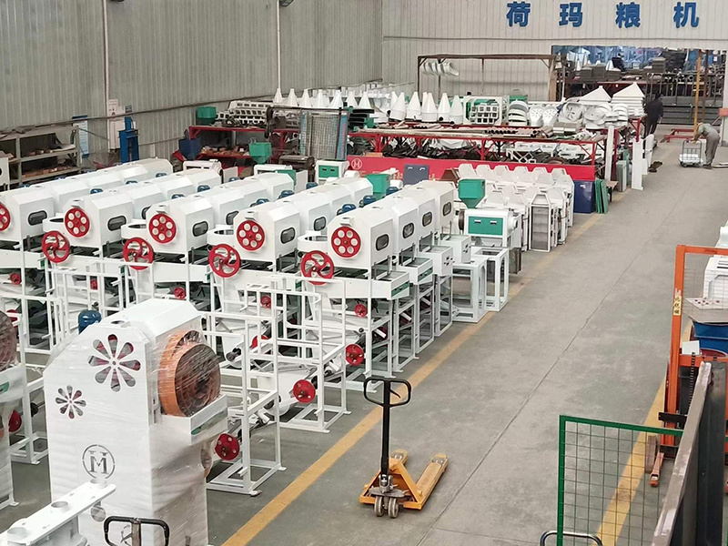
Workshop actual drawing
A workshop actual drawing refers to a detailed, accurate representation of an object, machine, or structure as it is designed and manufactured for use in a workshop or production environment. These drawings serve as the basis for fabricating, assembling, or installing the components involved in a project. The term "actual drawing" often implies that the drawing represents the real-world specifications of the parts or products, as opposed to conceptual or design-level sketches. These drawings are typically used by engineers, technicians, machinists, or builders during the manufacturing or construction process. Key Characteristics of a Workshop Actual Drawing: Precise Details: Workshop actual drawings provide exact dimensions, tolerances, and material specifications. These details are critical for ensuring that parts are manufactured or assembled correctly. Real-World Representation: Unlike preliminary design drawings or conceptual sketches, an actual drawing shows the exact shape, size, and construction of the component, structure, or system, as it will be built or assembled in the workshop. It may include specific notes on assembly instructions, welding processes, or finishing requirements. Scale and Accuracy: These drawings are typically made to scale to ensure that components fit together accurately. Dimensions on the drawing are proportional to the actual size of the parts. Detailed Views: Orthographic views (front, top, side), sectional views, and detail views are often used to show the component from different angles and provide extra information about features that might not be visible in a standard view. For example, if a part has internal holes or grooves, a sectional view will help convey that information. Material and Finishing Specifications: The drawing may include details about the materials used (e.g., steel, aluminum, plastic) and specific finishing requirements (e.g., coating, heat treatment, surface roughness) to ensure the part meets performance requirements. Manufacturing and Fabrication Information: Actual workshop drawings often contain information about manufacturing processes (e.g., machining, casting, welding, bending) and tools or machinery needed to produce the part. It may also include details about assembly procedures, fasteners, and tolerances (acceptable variations in dimensions) for each part or assembly.
Classification:
Detailed introduction
A workshop actual drawing refers to a detailed, accurate representation of an object, machine, or structure as it is designed and manufactured for use in a workshop or production environment. These drawings serve as the basis for fabricating, assembling, or installing the components involved in a project. The term "actual drawing" often implies that the drawing represents the real-world specifications of the parts or products, as opposed to conceptual or design-level sketches. These drawings are typically used by engineers, technicians, machinists, or builders during the manufacturing or construction process.
Key Characteristics of a Workshop Actual Drawing:
-
Precise Details:
- Workshop actual drawings provide exact dimensions, tolerances, and material specifications. These details are critical for ensuring that parts are manufactured or assembled correctly.
-
Real-World Representation:
- Unlike preliminary design drawings or conceptual sketches, an actual drawing shows the exact shape, size, and construction of the component, structure, or system, as it will be built or assembled in the workshop.
- It may include specific notes on assembly instructions, welding processes, or finishing requirements.
-
Scale and Accuracy:
- These drawings are typically made to scale to ensure that components fit together accurately. Dimensions on the drawing are proportional to the actual size of the parts.
-
Detailed Views:
- Orthographic views (front, top, side), sectional views, and detail views are often used to show the component from different angles and provide extra information about features that might not be visible in a standard view.
- For example, if a part has internal holes or grooves, a sectional view will help convey that information.
-
Material and Finishing Specifications:
- The drawing may include details about the materials used (e.g., steel, aluminum, plastic) and specific finishing requirements (e.g., coating, heat treatment, surface roughness) to ensure the part meets performance requirements.
-
Manufacturing and Fabrication Information:
- Actual workshop drawings often contain information about manufacturing processes (e.g., machining, casting, welding, bending) and tools or machinery needed to produce the part.
- It may also include details about assembly procedures, fasteners, and tolerances (acceptable variations in dimensions) for each part or assembly.
Previous:
Next:

 Language


